Bring Up: CAN Bus
Now that all of the software is installed and verified, the next major step is to setup hardware and firmware.
Understand the goal
At this point we want to have reliable communication with CAN devices. There are typically two failure modes that must be resolved:
There are same-model devices on the bus with the same device ID (devices have a default device ID of ‘0’).
CAN bus is not wired correctly / robustly.
This is why during hardware validation, you will likely have to isolate each device to assign a unique device ID.
Note
CTRE software has the ability to resolve device ID conflicts without device isolation, and CAN bus is capable of reporting the health of the CAN bus (see Driver Station lightening tab). However, the problem is when both root-causes are occurring at the same time, this can confuse students who have no experience with CAN bus systems.
Note
Many teams will preassign and update devices (Talon SRXs for example) long before the robot takes form. This is also a great task for new students who need to start learning the control system (with the appropriate mentor oversight to ensure hardware does not get damaged).
Note
Label the devices appropriately so there is no guessing which device ID is what. Don’t have a label maker? Use tape and/or Sharpie (sharpie marks can be removed with alcohol).
Warning
Talon SRX and Talon FX must use unique device IDs for Phoenix API to function correctly. This design decision was made so that teams could use the existing TalonSRX class for control.
Check your wiring
Specific wiring instructions can be found in the user manual of each product, but there are common steps that must be followed for all devices:
If connectors are used for CANBus, tug-test each individual crimped wire one at a time. Bad crimps/connection points are the most common cause of intermittent connection issues.
Confirm red and black are not flipped. Motor Controllers typically are not reverse power protected.
Confirm battery voltage is adequate (through Driver Station or through voltmeter).
Manually inspect and confirm that green-connects-to-green and yellow-connects-to-yellow at every connection point. Flipping/mixing green and yellow is a common failure point during hardware bring up.
Confirm breakers are installed in the PDP where appropriate.
Measure resistance between CANH and CANL when system is not powered (should measure ~60Ω). If the measurement is 120Ω, then confirm both RIO and PDP are in circuit, and PDP jumper is in the correct location.
Power up and check LEDs
If you haven’t already, power up the platform (robot, bench setup, etc.) and confirm LEDs are illuminated (at all) on all devices.
You may find many of them are blinking or “blipping” red (no communication).
Tip
If you are color-blind or unable to determine color-state, grab another team member to assist you.
Note
If using Ribbon cabled Pigeon IMUs, Pigeon LEDs will reflect the ribbon cable, not the CAN bus. At which point any comm issue with Pigeon will be resolved under section Bring Up: Pigeon IMU.
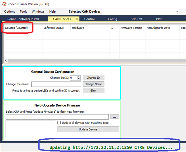
Open Phoenix Tuner
Navigate to the CAN devices page.
This capture is taken with no devices connected to the roboRIO. roboRIO will take around 30 seconds to boot.
Tip
There is a modernized version called Tuner X that is available for Windows and Android devices (works with Phoenix 5 and Phoenix Pro).
LEDs are red – now what?
We need to rule out same-id versus bad-bus-wiring. There are two approaches. Approach 1 will help troubleshoot bad wiring and common IDs. Approach 2 will only be effective in troubleshooting common IDs. But this method is noteworthy because it is simple/quick (no wiring changes, just pull breakers).
The specific instructions for changing device ID are in the next section. Review this if needed.
Approach 1 (best)
Procedure:
Physically connect CAN bus from roboRIO to one device only. Circumvent your wiring if need be.
Power boot robot/bench setup.
Open Phoenix Tuner and wait for connection (roboRIO may take ~30 seconds to boot)
Open CAN devices tab
Confirm if CAN device appears.
Use Tuner to change the device ID
Label the new ID on the physical device
Repeat this procedure for every device, one at a time.
If you find a particular device where communication is not possible, scrutinize device’s power and CAN connection to roboRIO. Make the test setup so simple that the only failure mode possible is within the device itself.
Note
Typically, there must be two termination resistors at each end of the bus. One is in the RIO and one is in the PDP. But during bring-up, if you keep your harness short (such as the CAN pigtail leads from a single Talon) then the internal resistor in the RIO is adequate.
Approach 2 (easier)
Procedure:
Leave CAN bus wiring as is.
Pull breakers and PCM fuse from PDP.
Disconnect CAN bus pigtail from PDP.
Pick the first device to power up and restore breaker/fuse/pigtail so that only this CAN device is powered.
Power boot robot/bench setup.
Open Phoenix Tuner and wait for connection (roboRIO may take ~30 seconds to boot)
Open CAN devices tab
Confirm if CAN device appears. If device does not appear, scrutinize device’s power and CAN connection to roboRIO.
Use Tuner to change the device ID
Label the new ID on the physical device
Repeat this procedure for every device.
If you find a particular device or section of devices where communication is not possible, then the CAN bus wiring needs to be re-inspected. Remember to “flick” / “shake” / “jostle” the CAN wiring in various sections to attempt to reproduce red LED blips. This is a sure sign of loose contact points.
If you are able to detect and change device ID on your devices individually, begin piecing your CAN bus together. Start with roboRIO <—-> device <—> PDP, to ensure termination exists at both ends. Then introduce the remaining devices until a failure is observed or until all devices are in-circuit.
If introducing a new device creates a failure symptom, scrutinize that device by replacing it, inspecting common wires, and inspecting power.
Note
If 2014 PDP is the only device that does not appear or has red LEDs, see PDP boot up section for specific failure mode.
Note
If ribbon cable Pigeon does not appear, it likely is because Talon has old firmware.
At the end of this section, all devices should appear (notwithstanding the above notes) and device LEDs should not be red. PCM, Talon, Victor, Pigeon, and CANifier typically blink orange when they are healthy and not controlled. PDP may be orange or green depending on its sticky faults.
Set Device IDs
Note
A CTRE device can have an ID from 0 to 62. If you select an invalid ID, you will generally get an immediate prompt.
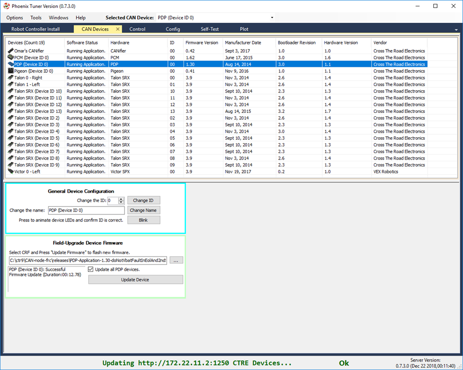
Below we see several devices, however the physical robot has 19 actual devices. Because all the Talons have a device ID of ‘0’, the do not show up as unique hardware. This must be resolved before you can attempt utilizing them.
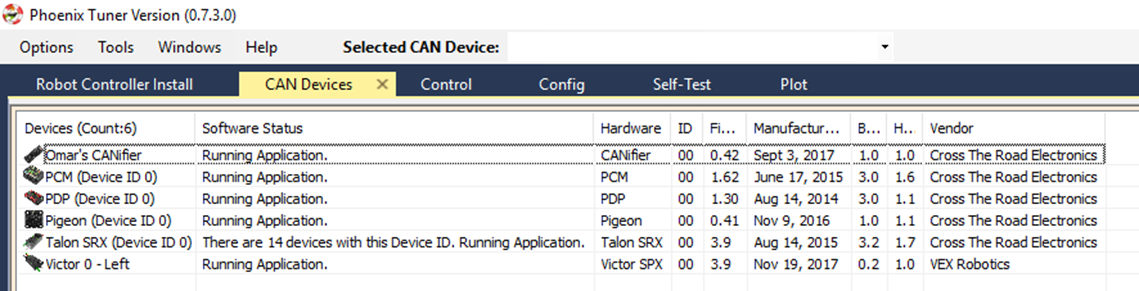
Note
We recommend isolating each device and assigning a unique ID first. But in the event there is a conflict, expect an entry mentioning multiple devices. When selecting a device, the actually physical device selected will be the conflict-id device that booted last. You can use this information to control which Talon you are resolving by power cycling the conflict device, then changing its ID in Tuner.
Select the device and use the numeric entry to change the ID. Note the text will change blue when you do this. Then press “Change ID” to apply the changes.
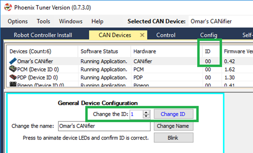
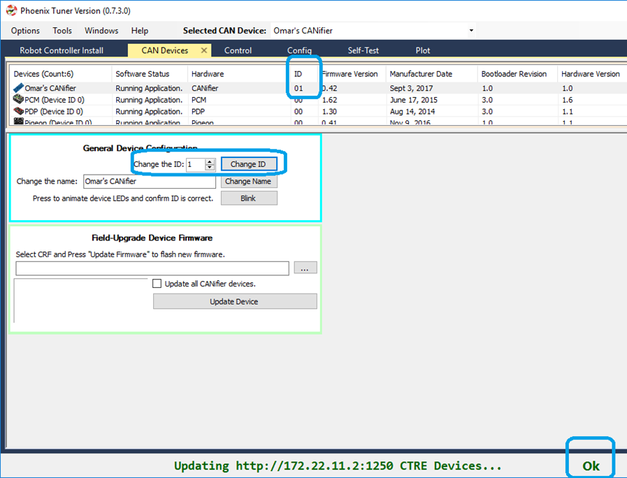
If operation completes, an OK will appear in the bottom status bar (this is true of all operations). Also note the ID has updated in the device list, and the ID text is now black again.
Tip
All production CTRE hardware ships with a default ID of ‘0’. As a result, it is useful to start your devices at device ID ‘1‘, so you can cleanly add another out-of-box device without introducing a conflict.
When complete, make sure every device is visible in the view. Use the Blink button on each device to confirm the ID matches the expected physical device.
Note
The device count is present in the top left corner of the device list. Use this to quickly confirm all devices are present.
Note
If ribbon-cabled pigeon is not present, then the host talon likely has old firmware.
Field upgrade devices
At this point all devices are present, but the firmware is likely old.
The 2020 season has 20.X firmware for Talon FX, Talon SRX, Victor SPX, CANCoder, CANifier, and Pigeon IMU. Moving forward, the first number of the version will represent the season (next year’s 2021 firmware will be 21.X).
20.X firmware is required for all motor controllers and CANCoder. 20.X is also recommended for CANifier and Pigeon IMU.
Note
Latest PDP is 1.40. PDP typically ship with 1.30. 1.40 has all of the signals read by the WPILib software, and will tare the current measures so current will read 0 instead of ~1-2 amps when there is no current-draw. Updating to 1.40 is recommended.
Note
Latest PCM is 1.65. PCM typically ship with 1.62. Firmware 1.65 has an improvement where hardware-revision 1.6 PCMs will not-interrupt compressor when blacklisting a shorted solenoid channel. Older revisions will pause the compressor in order to safely sticky-fault, new revisions have no need to do this (if firmware is up to date).
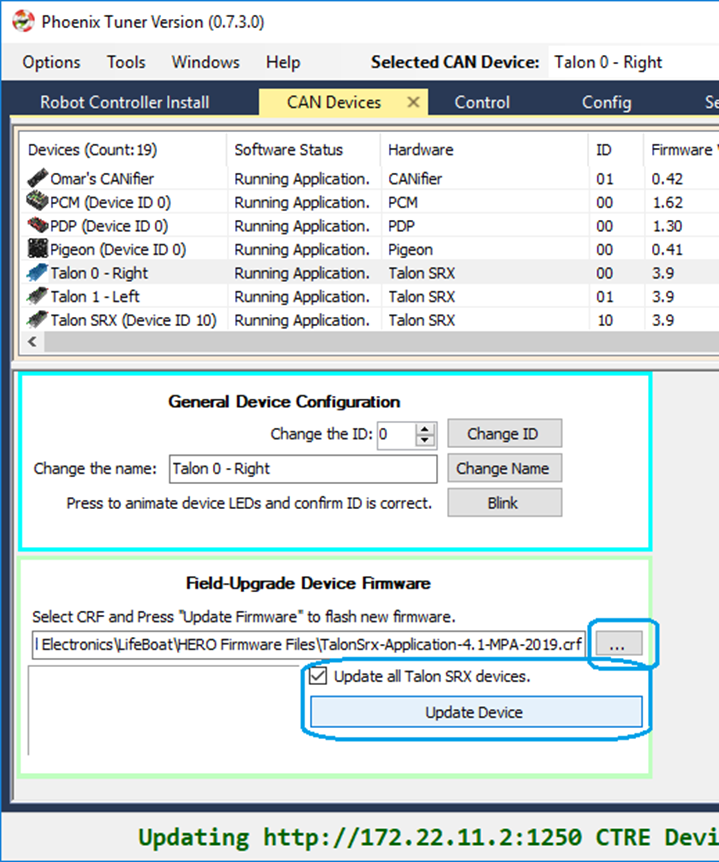
Select the CRF under the Field-upgrade section then press Update Device. The CRFs are available in multiple places, and likely are already on your PC. See section Device Firmware Files (crf).
If there are multiple devices of same type (multiple Talon SRXs for example), you may check Update all devices. This will automatically iterate through all the devices of the same type, and update them. If a device field-upgrade fails, then the operation will complete. Confirm Firmware Version column in the device list after field-upgrade.
Note
Each device takes approximately 15 seconds to field-upgrade.
When complete every device should have latest firmware.
Pick device names (optional)
The device name can also be changed for certain device types: - CANifier - Pigeon IMU (on CAN bus only) - Talon SRX and Victor SPX
Note
PDP and PCM do not support this.
Note
Ribbon cabled Pigeon IMUs do not support this.
Note
To re-default the custom name, clear the “Name” text entry so it is blank and press “Save”.
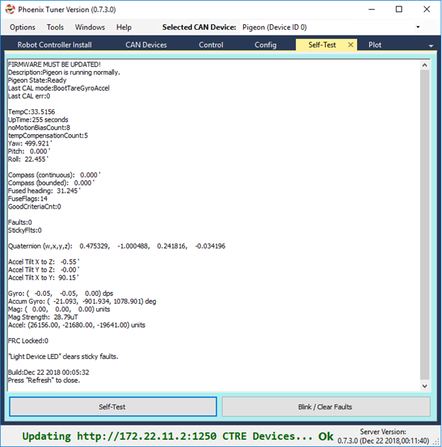
Self-test Snapshot
At this point every device should be present on the bus, and updated to latest. This is an opportune time to test the Self-test Snapshot feature of each device.
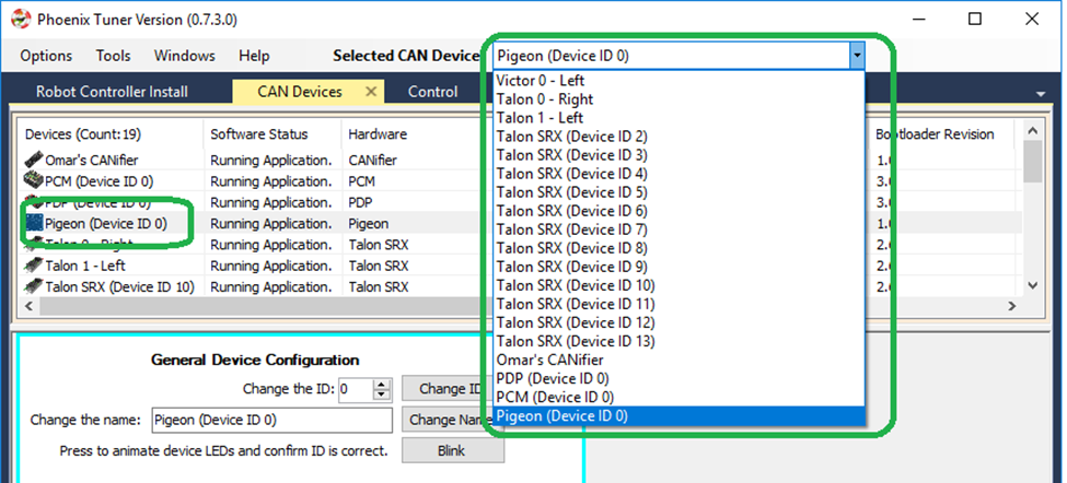
Select each device either in the device list, or using the dropdown at the center-top. This dropdown is convenient as it is accessible regardless of how the tabs are docked with Tuner.
Note
If you press the “Selected CAN device” text next to dropdown, you will be taken back to the CAN Devices tab.
Navigate to the Self-test Snapshot tab. If Self-test Snapshot tab is not present, use the Windows menu bar to reopen it.
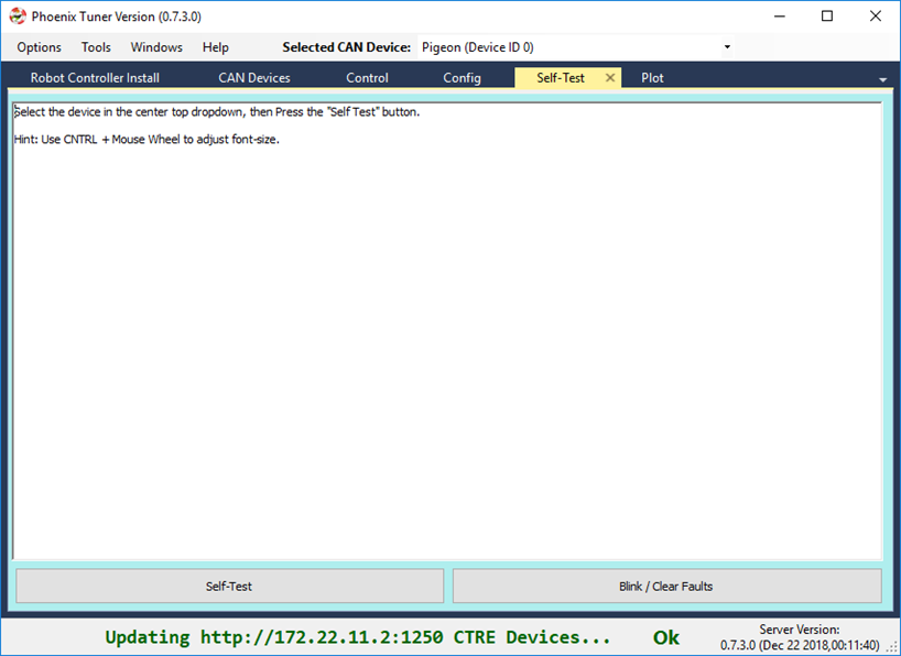
Press Self-test Snapshot button and confirm the results.
Note
This Pigeon has not had its firmware updated, this is reported at the top.
You can also use the Blink/Clear faults button to blink the selected device and clear any previously logged sticky faults.
Driver Station Versions Page
It is worth mentioning there is basic support of reporting the CAN devices and their versions in the diagnostics tab of the Driver Station.
If there is a mixed collection of firmware versions for a given product type, the version will report “Inconsistent”.
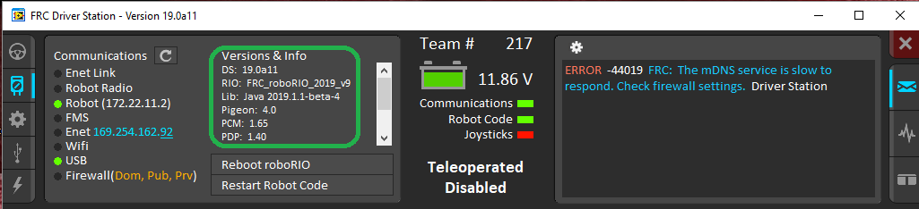
Note
The recommended method for confirming firmware versions is to use Phoenix Tuner.
Note
There is a known issue where ribbon-cabled Pigeons may erroneously report as a Talon. Since this is not a critical feature of the Driver Station, this should not be problematic for FRC teams.